Telecoms Network Bandwidth Planning
📡 Telecom Transmission Planning & Aggregation Design Challenge Overview
This project documents the solution to a telecommunications transmission planning challenge involving bandwidth calculation, Busy Hour Traffic (BHT) engineering, microwave backhaul dimensioning, redundancy planning, and future capacity growth.
The objective was to design a resilient aggregation network for multiple BTS sites distributed across an urban, suburban, and inter-city corridor, while respecting utilization, latency, and availability constraints.
This project demonstrates:
Practical telecom traffic engineering
Microwave transmission planning using Packet Link Aggregation (PLA)
Redundancy and protection design
Capacity planning with future growth considerations
Clear documentation and topology visualization
📋 Challenge Statement
Each student was assigned a logical cluster of 65 live BTS sites distributed across a dense urban core, suburban districts, and an inter-city highway corridor. The BTS sites were grouped under five aggregation hubs (Hub A, Hub B, Hub C, Hub D, and Hub E).
These hubs represent real aggregation locations where BTS traffic is backhauled using a hybrid transmission network of fiber and licensed microwave links. Hub A is the only hub directly connected to the BSC at the regional switching center and also provides onward connectivity to the IP core for packet services.
For each BTS, carried traffic is split across:
- 2G (voice)
- 3G (packet data)
- 4G (high-speed data and real-time services)
Students were required to:
- Calculate the total bandwidth per BTS
- Engineer the network based on Busy Hour Traffic (BHT)
- Ensure no link exceeds 70% utilization
- Dimension uplinks from Hub B, C, D, and E toward Hub A
- Determine total bandwidth required on the Hub A – BSC link
Additional Design Constraints
-
Redundancy Requirement:
The network must meet a 99.95% availability target. If any single uplink from Hub B, C, D, or E to Hub A fails, traffic must be rerouted through other hubs using protection links with 30% additional headroom and no oversubscription. -
Latency Constraint:
4G traffic must not traverse more than two hub hops to reach Hub A under both normal and failure conditions. Each hub-to-hub hop introduces 2 ms latency. -
Future Planning Rule:
All links must be dimensioned to support a 25% traffic growth projected over the next 18 months, without requiring upgrades.
📘 Challenge Description
Each student was assigned 65 live BTS sites, grouped under five aggregation hubs:
Hub A
Hub B
Hub C
Hub D
Hub E
Key constraints:
Each BTS carries 2G (voice), 3G (packet data), and 4G (high-speed & real-time services)
Traffic values represent Average Hour Traffic
Network must be engineered for Busy Hour Traffic (BHT)
No transmission link should exceed 70% utilization
Hub A is the only hub directly connected to the BSC and IP core
Aggregation is performed using fiber and licensed microwave links
🧮 Methodology 1️⃣ Total Bandwidth per BTS
For each BTS, total bandwidth was calculated by summing:
2G Traffic + 3G Traffic + 4G Traffic
2️⃣ Total Busy Hour Traffic per Hub
For each hub:
The total bandwidth of all 13 BTSs under that hub was summed
This represents the Busy Hour Traffic (BHT) for the hub
3️⃣ Future Traffic Growth
A 25% projected traffic growth over 18 months was applied:
Projected Traffic = Current BHT × 1.25
📊 Busy Hour Traffic Results Hub Current BHT (Mbps) Projected BHT (+25%) Hub A 637 Mbps 796 Mbps Hub B 640 Mbps 800 Mbps Hub C 880 Mbps 1100 Mbps Hub D 869 Mbps 1086 Mbps Hub E 738 Mbps 922 Mbps 🔗 Packet Link Aggregation (PLA)
Packet Link Aggregation (PLA) is a microwave transmission technique used to bundle multiple physical radio channels into a single logical link.
In this project:
Each PLA represents a 512+ Mbps licensed microwave channel
Multiple PLAs are aggregated to meet traffic demand
Utilization is engineered to remain ≤ 70% during Busy Hour
PLA allows scalable capacity without deploying new radios
Note: PLA in this project refers to Packet Link Aggregation, not Peak Load Allowance.
🛜 Uplink Capacity Engineering
For each hub (B–E), uplinks toward Hub A were dimensioned using:
Busy Hour Traffic
70% utilization constraint
Future traffic growth
PLA-based aggregation
Example:
2 × 512 Mbps PLA = 1024 Mbps logical uplink
Utilization calculations ensured all links remained within safe operational thresholds.
📊 Link Utilization Calculation
Transmission links were engineered to ensure that utilization does not exceed 70% during Busy Hour, in line with standard telecom planning practices.
Link utilization was calculated using the formula:
Utilization (%) = (Traffic Load / Total Uplink Capacity) × 100
Example Calculation
If a hub has a Busy Hour traffic load of 800 Mbps and is provisioned with 2 × 512 Mbps PLA links:
Total Uplink Capacity = 1024 Mbps
Utilization = (800 / 1024) × 100 ≈ 78%
In this case, additional PLA capacity would be required to bring utilization within acceptable limits.
All final uplink designs in this project were dimensioned to operate at ≤ 70% utilization under Busy Hour conditions.
🔁 Redundancy & Protection Design
To meet a 99.95% availability target, the network was designed with inter-hub protection paths:
If any single uplink to Hub A fails, traffic can reroute through other hubs
Protection links include 30% additional headroom
Oversubscription is not permitted
Dotted links in the topology represent redundancy paths
⏱️ Latency Constraint Validation
4G traffic is latency-sensitive
Maximum allowed hops to Hub A: 2 hops
Each hub-to-hub hop introduces 2 ms latency
✔ All normal and failure paths were validated to remain within latency limits.
🧱 Hub A – BSC Link Dimensioning
Hub A aggregates traffic from:
Hub A local BTSs
Hub B, C, D, and E
Total aggregated Busy Hour traffic (including growth) was used to dimension the Hub A → BSC uplink, ensuring:
≤ 70% utilization
Sufficient PLA capacity
Support for redundancy scenarios
🗺️ Network Topology Aggregation & Redundancy Design
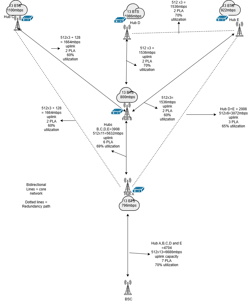
Solid lines → Core transmission paths
Dotted lines → Redundant protection paths
📝 Calculation Evidence
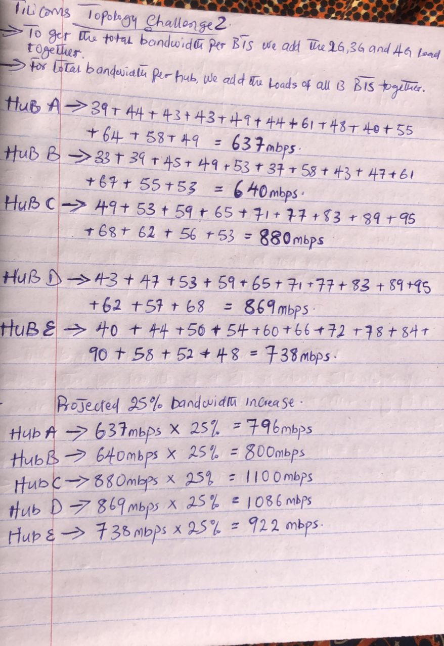
Handwritten calculations were used to:
Validate BTS totals
Derive hub-level Busy Hour Traffic
Apply future growth projections
🧠 Key Takeaways
Real-world telecom transmission planning requires strict utilization discipline
PLA is critical for scalable microwave backhaul
Redundancy must be engineered, not assumed
Latency constraints strongly influence topology decisions
Capacity planning must always account for future growth
🧰 Tools Used
Manual traffic engineering calculations
draw.io – topology design
GitHub Pages / Markdown – documentation
Telecom transmission planning principles
📌 Author
Precious Anyanwu Aspiring Network / Cloud / Security Engineer Documenting hands-on telecom and cybersecurity projects